

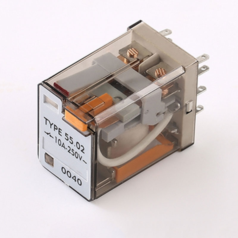
Electromagnetic relay is an electronic control device that consists of a control system (also called the input circuit) and a controlled system (also called the output circuit). It is commonly used in automatic control circuits, functioning as an “automatic switch” that uses relatively small current and low voltage to control larger current and higher voltage. Therefore, it plays roles in automatic regulation, safety protection, and circuit switching in electrical systems.
Electromagnetic relays are widely applied in aviation, aerospace, marine, household appliances, and other fields. They primarily perform functions such as signal transmission, control execution, and system power distribution, making them one of the key electronic components in various systems.
The working principle of electromagnetic relays
I.What is electromagnetic relay?
In simple terms, an electromagnetic relay acts like a “smart switch” that uses small currents to control large currents. It consists of two parts:
- Control side (low-current part): Works like the “remote control” of the switch
- Controlled side (high-current part): Functions as the actual “high-power switch”
How it works:
When a small current (e.g., 5V voltage) is applied to the control side, it generates magnetic force to close the switch, thereby controlling the high-current circuit (e.g., 220V appliances). It’s like using a small button to control all the lights in a building.
Main functions:
✓ Safely controls high current with low current
✓ Isolates high and low voltage circuits for safety
✓ Enables automatic control (e.g., automatic power-off when reaching set temperature)
Common applications:
• Household appliances: Automatic control in AC units, refrigerators
• Automotive: Control of headlights, horns
• Industrial: Automatic start/stop of machinery
• Smart home: Remote control of appliances
This “small controls large” characteristic makes relays indispensable “safety guardians” in modern circuit control systems.
Ⅱ. How does electromagnetic relay works?
An electromagnetic relay works like an electrically-controlled mechanical switch through these key steps:
- Control Signal Activation
- When a small voltage (e.g., 5V DC) is applied to the relay’s coil (input side), it becomes an electromagnet
- Example: A microcontroller’s 3.3V signal can trigger a 12V relay
- Magnetic Field Generation
- The energized coil creates a magnetic field
- This pulls a movable armature (metal lever) toward the electromagnet
- Contact Switching
- The armature physically moves the contacts (output side)
- Contacts either:
✓ Close (NO type) – Connects the high-power circuit
✓ Open (NC type) – Disconnects the high-power circuit
- Current Control
- Now the small control current indirectly governs the large load current
- Typical load examples:
• 10A/240V AC mains for appliances
• 30A/12V DC for automotive systems
- Reset Mechanism
- When control power is removed:
- Spring returns armature to original position
- Contacts revert to default state
- When control power is removed:
Visual Analogy:
Imagine using a small water flow (control current) to tilt a lever that opens a dam gate (load current) – minimal effort controls massive power.
Key Advantages:
• Complete electrical isolation between control and load
• No leakage current when off (unlike semiconductors)
• Handles both AC/DC and high-voltage switching
This reliable “electro-mechanical handshake” makes relays perfect for safety-critical applications where solid-state devices might fail.
Ⅲ. electromagnetic relay wiring diagram
Relays generally have a sensing mechanism (input part) that responds to certain input variables (such as current, voltage, power, impedance, temperature, pressure, speed, light, etc.); an actuating mechanism (output part) capable of switching the controlled circuit “on” or “off”; and an intermediate mechanism (driving part) between the input and output parts that provides coupling isolation, functional processing of the input, and drives the output part. A relay is a device that can produce a predetermined transition in one or more electrical output circuits when the input (or excitation) meets specified conditions. In terms of its role in the controlled circuit, it functions like a “switch,” but it is not manually operated—instead, it is an automatic remote control component.
8-pin relay wiring diagram:
Power connects to power supply. Pins 2 and 7 are one set of normally open (NO) and one set of normally closed (NC). Choose based on your needs. The reset is used to clear the timer relay (Chinese version, not that difficult). Unlike the regular type that cuts power to control the timer relay, this one has an external control terminal.
If it’s 220V, it depends on how you use it. For example, if you’re controlling a light:
- Pins 2 and 7 connect to 220V (no distinction between live and neutral).
- For delayed turn-on: Pin 8 connects to live, Pin 6 connects to the light, and the other end of the light connects to neutral.
- For delayed turn-off: Pin 8 connects to live, Pin 5 connects to the light, and the other end of the light connects to neutral.
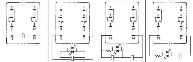
Most 8-pin relays have two pins for the coil, while the remaining six pins are divided into two groups, each consisting of three pins: one normally open (NO) contact, one normally closed (NC) contact, and one common terminal. The relay should have a wiring diagram indicating which two pins are for the coil’s positive and negative, and which pins correspond to the NO/NC contacts. The actual wiring depends on whether you need the NO or NC contact. For DC coils, make sure to connect the correct polarity (positive and negative).
Ⅳ. How to use electromagnetic relay?
An electromagnetic relay is an electrically operated switch that uses an electromagnet to mechanically control the opening and closing of contacts. Here’s how to use it properly:
1. Identify the Relay Terminals
- Coil terminals (usually labeled A1 & A2 or + & –) – Apply voltage here to energize the relay.
- Common (COM) terminal – The central contact that switches between NO and NC.
- Normally Open (NO) terminal – Connects to COM when the relay is energized.
- Normally Closed (NC) terminal – Disconnects from COM when the relay is energized.
2. Connect the Control Circuit (Coil Side)
- For DC relays, ensure correct polarity (A1 = +, A2 = -).
- For AC relays, polarity does not matter.
- Provide the rated coil voltage (e.g., 5V, 12V, 24V, 220V) to activate the relay.
3. Connect the Load Circuit (Contact Side)
- For Normally Open (NO) operation:
- Connect COM to one side of the load (e.g., motor, lamp).
- Connect NO to the power supply.
- When energized, the circuit closes, powering the load.
- For Normally Closed (NC) operation:
- Connect COM to one side of the load.
- Connect NC to the power supply.
- When energized, the circuit opens, cutting off power.
4. Example Applications
- Switching high-voltage devices (e.g., motors, heaters) using a low-voltage signal (e.g., from a microcontroller).
- Automation control (e.g., turning lights on/off with a sensor).
- Safety cutoffs (e.g., emergency stop circuits).
5. Precautions
- Check voltage/current ratings to avoid relay damage.
- Use a flyback diode (for DC relays) to protect against voltage spikes.
- Ensure proper insulation when handling high-voltage loads.
By following these steps, you can safely and effectively use an electromagnetic relay for various control applications.
Conclusion
The electromagnetic relay is a versatile and essential component in electrical and electronic systems, serving as a reliable bridge between low-power control circuits and high-power loads. Its ability to isolate and switch circuits ensures safe and efficient operation across various applications—from industrial automation to household appliances. By understanding its working principles, correct wiring methods, and practical usage considerations, users can effectively integrate relays into their projects for enhanced control and protection. Whether for simple switching tasks or complex automation systems, the electromagnetic relay remains a fundamental and indispensable device in modern electrical engineering.
References
1. Omron (Japan)
- Relay Technical Guide – Covers relay basics, selection criteria, and application examples.
🔗 Omron Relay Technical Guide - Signal Relay Application Manual – Focuses on PCB-mounted relays for low-power applications.
🔗 Omron Signal Relay Manual
2. TE Connectivity (USA/Switzerland)
- Relay Fundamentals & Applications – Explains relay types, contact materials, and switching characteristics.
🔗 TE Connectivity Relay Guide - Power Relay Selection Guide – Helps choose relays for industrial and automotive applications.
🔗 TE Power Relay Selection
3. Panasonic (Japan)
- Relay Technical Handbook – Includes relay principles, failure modes, and circuit design tips.
🔗 Panasonic Relay Handbook - Automotive Relay Application Notes – Covers relays for vehicle systems.
🔗 Panasonic Automotive Relays
4. Siemens (Germany)
- Industrial Relay Manual – Focuses on relays for automation and control systems.
🔗 Siemens Relay Documentation - SIRIUS Relay Selection Guide – Helps choose relays for motor control and power switching.
🔗 Siemens SIRIUS Relays
5. Schneider Electric (France)
- Relay Application Guide – Discusses relays for energy management and automation.
🔗 Schneider Relay Guide - Zelio & RM Relays Manual – Covers electromechanical and solid-state relays.
🔗 Schneider Zelio Relays
6. Fujitsu (Japan)
- Relay Selection & Usage Guide – PCB relay applications in telecom and IoT.
🔗 Fujitsu Relay Guide
These resources provide in-depth technical details, helping engineers select and implement relays correctly. For specific models, always refer to the manufacturer’s datasheet.
Would you like a specific focus (e.g., automotive, industrial, or PCB relays)?